A resistance temperature detector (RTD) is basically a resistance thermometer that measures temperature. RTDs are replacing thermocouples because of their better accuracy and repeatability. RTD works on the principle that the resistance of an RTD element changes with temperature. RTDs are used to measure industrial temperatures from 200 to 1200 °C. RTDs require external power to operate.
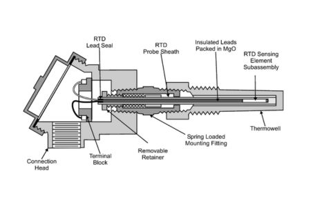
Structure of the resistance temperature sensor
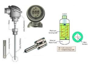
Most resistance temperature sensors consist of a spiral wire wound around a ceramic core. RTD elements are mainly composed of platinum, nickel, or copper. RTDs are made of pure metals or certain alloys that increase in resistance with increasing temperature and decrease as the temperature decreases.
The resistivity of the metals used in RTDs increases with increasing temperature. The resistive properties of the material will match the length and cross-section required to achieve a specific RTD value. RTD elements are basically long, spring-like wires wrapped in insulation and encased in a metal sheath. Insulation is used to prevent short circuits between the wire and the metal sheath.
How does a resistance temperature sensor work?
The resistivity of the RTD material will increase linearly with temperature. The resistance of an RTD element is measured by passing an alternating current through it. Due to the current, a certain voltage is induced in the metal, which can be measured with a voltmeter. The voltage reading is then converted to temperature.
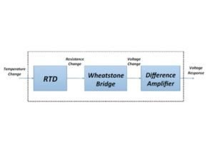
RTDs are resistance devices, and when current passes through them, the resistance of the material can change, causing measurement errors. To avoid this problem, RTDs are primarily connected to a Wheatstone bridge network with additional bridge wires to compensate the wire or connect to a constant current source.
Various wiring methods in RTD
To perform an RTD measurement, the resistance value must be converted and that value transferred to the instrument. Wires are used to transmit measurements, and wires are made of copper. We know that wires have resistance, so when a measurement is transmitted, that resistance changes the measurement. Different types of cable connections are used to solve this problem, in the following sections we will see different types of RTD sensor wiring diagrams.
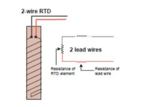
2-wire RTD
This is a simple wiring method that connects the circuit to two wires. Two RTD leads are used to connect to the device. Current will flow through the RTD and voltage will be measured. The disadvantage of this cable is that due to the increased resistance, heat builds up in the RTD, which affects the measurement.
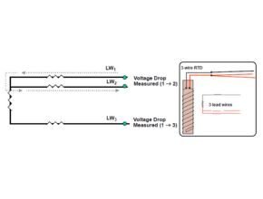
3 wire RTD
In the three-wire method, three wires are used to reduce the effect of resistance on the measurement. In this case, an additional wire will be used and connected to the RTD switch. Therefore, there will be two measurement circuits, one of which will serve as a reference. The third wire used should be similar to the other two, so the two wires will have the same resistance and cancel each other out. This is similar to a two-wire RTD, the current will flow through the RTD and the voltage will be measured. The third wire will compensate for the resistance of the wire.
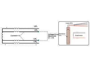
4-wire RTD
This type of RTD wire is used when high accuracy is required, this type of RTD wire is insensitive to wire resistance and supplies current to one set of wires and voltage to the other. Therefore, there will be no voltage drop in the measurement leads and the resistance of the leads will not be part of the measurement. The output voltage will be proportional to the RTD impedance.
Types of Resistance Temperature Detector
Wire wound RTD
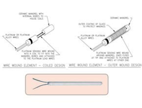
This type of RTD is made by wrapping a platinum wire around a ceramic column and covering it with additional glass or plastic. This type of RTD element is very reliable compared to thin film types. We can use this type of RTD in many applications, but it suffers if used in a high-vibration area.
Film style RTD

Thin film RTDs are made by depositing a thin layer of platinum on a ceramic substrate. Then create a pattern that provides the circuit and is configured to provide some resistance. The wires are then connected and the element is then coated to protect the platinum film and wire connections. This type of RTD has a better response time than the coiled RTD.
How to check the resistance of a temperature detector?
We can check the RTD sensor with a multimeter and connect the multimeter to the RTD pins to test the RTD. After measuring, compare the resistance with the manual value, which will be non-zero and infinity if the RTD is working.
How is RTD resistance measured?
RTDs are made of a stiff metal wire whose resistance increases with temperature. Resistance is proportional to length and inversely proportional to cross-section.
- R = ?L / A? = 1 / e.n.u
- R = resistance e = load
- ? = resistance n = electron density
- L = wire length, u = electronic mobility
- A = area of ??the cable
n.u will decrease with increasing temperature, so resistance will increase with increasing temperature.
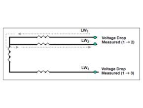
This is a picture of a 3-wire RTD, a small known current will be transmitted to LW1 and LW2 and then the voltage drop is measured.
Measured V 1 ? 3 = RTD element V + main cable V 1 & 3 = total IR
The resistance of the RTD element plus the main cable is equal to the measured voltage drop divided by the known current.
To find the RTD element voltage, the main cable voltages LW1 and LW3 must be subtracted from the measured voltages at LW1 and LW3. The LW1 and LW2 voltages found in step 1 can be used as a close approximation to the LW1 and LW3 voltages.
Element VRTD = Measured V 1 ? 3 – V of main wires 1 & 2
Element R RTD = V of element RTD ÷ I
How is RTD resistance measured?
RTDs are made of a stiff metal wire whose resistance increases with temperature. Resistance is proportional to length and inversely proportional to cross-section.
- R = ?L / A? = 1 / e.n.u
- R = resistance e = load
- ? = resistance n = electron density
- L = wire length, u = electronic mobility
- A = area of ??the cable
n.u will decrease with increasing temperature, so resistance will increase with increasing temperature.
Resistance Temperature Detector Applications
- Bio-reactors
- Air conditioning and refrigeration servicing
- Medical research
- Foodservice processing
- Textile production
Advantages of Resistance Temperature Detector
- Stable over time
- Wide temperature range
- Small size
- Fast response
- Accurate
- Temperature measurements can be repeated
- Resistant to contamination
- Resistant to corrosion
Limitations of Resistance Temperature Sensors
- High cost
- Slower response
- Less sensitive to small changes in temperature
- Vibration may affect the measurement
- Fragile
Conclusion
From the article “Definition, Working Methods and Type of Resistance Temperature Detector” that we described above, the following conclusions can be drawn:
- A resistance temperature detector (RTD) is basically a resistance thermometer used to measure temperature. RTDs are replacing thermocouples because of their better accuracy and repeatability.
- Most resistance temperature sensors consist of a spiral wire wound around a ceramic core. RTD elements are mainly composed of platinum, nickel or copper.
- The resistivity of the RTD material will increase linearly with temperature. The resistance of an RTD element is measured by passing an alternating current through it. Due to the current, a certain voltage is induced in the metal, which can be measured with a voltmeter. The voltage reading is then converted to temperature.
- There are 3 ways to connect the wires in a resistance temperature detector, namely: 2 wires, 3 wires,
wires
References : wma.co.id